
Bridge vs Full-Wave Rectifiers: A Comparative Analysis
2025-07-11
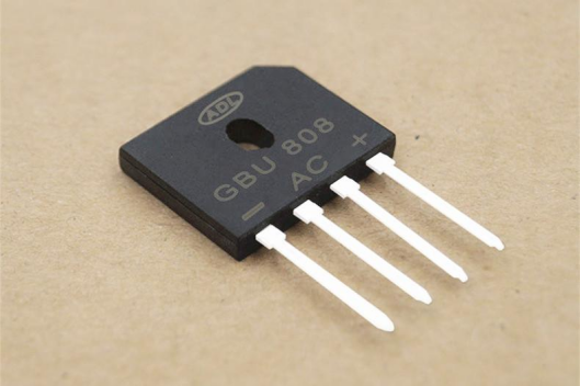 In modern electronic circuits, rectifiers are key devices for converting alternating current (AC) to direct current (DC). Bridge rectifiers and full-wave rectifiers are two common types of rectification methods, each with distinct characteristics in terms of structure, principles, performance, and application fields. This article will provide a detailed introduction to the basic principles, common applications, and popular models of these two types of rectifiers, and conduct a comparative analysis to help readers better understand their differences and suitable scenarios.
Overview of Bridge Rectifiers
A bridge rectifier is a rectification device that uses four diodes to form a bridge circuit, capable of converting both the positive and negative half-cycles of AC into DC. It is widely used in various applications that require the conversion of AC to DC, favored for its simple structure and high efficiency.
The working principle of a bridge rectifier is based on the unidirectional conductivity of diodes. During the positive half-cycle of the AC, one pair of diagonal diodes conducts, allowing current to flow through the load. During the negative half-cycle, the other pair of diagonal diodes conducts, with the current still flowing in the same direction through the load. This alternating conduction ensures that the output current remains in a single direction, achieving full-wave rectification.
Bridge rectifiers are suitable for a variety of application scenarios, including but not limited to:
- Power adapters: Providing stable DC power for small electronic devices.
- Electric vehicle chargers: Converting AC to DC to charge electric vehicle batteries.
- Industrial power supplies: In industrial equipment where high efficiency and high stability are required, bridge rectifiers are the preferred choice.
Popular Bridge Rectifier Models
- 1N4007: With a voltage rating of 1000V and a maximum rectification current of 1A, it is suitable for high-voltage, low-current applications.
- GBU5: With a voltage rating of 50V and a maximum rectification current of 5A, it is suitable for medium-power applications.
- GBU10: With a voltage rating of 100V and a maximum rectification current of 10A, it is suitable for higher-power power supply circuits.
Overview of Full-Wave Rectifiers
A full-wave rectifier is a rectification method that uses both the positive and negative half-cycles of AC to produce a unidirectional output. It is typically implemented using a center-tapped transformer and two diodes, or through a bridge structure (i.e., full-bridge rectification).
The working principle of a full-wave rectifier involves using a center-tapped transformer to split the AC into two half-cycles, with each half-cycle being conducted by one diode. During the positive half-cycle, the upper half of the transformer outputs a positive voltage, and one diode conducts, allowing current to flow to the load. During the negative half-cycle, the lower half of the transformer outputs a negative voltage, and the other diode conducts, with the current still flowing in the same direction to the load.
The application scenarios of full-wave rectifiers mainly include:
- Traditional linear power supplies: In applications where high-quality DC is required, such as power supplies for high-end audio amplifiers.
- Household appliances: Such as power adapters and chargers, which are widely used due to their low cost.
Popular Full-Wave Rectifier Models
- 1N4004: With a voltage rating of 400V and a maximum rectification current of 1A, it is suitable for medium-voltage, low-current applications.
- 1N4005: With a voltage rating of 600V and a maximum rectification current of 1A, it is suitable for high-voltage, low-current applications.
Bridge Rectifier vs. Full-Wave Rectifier
Although both bridge rectifiers and full-wave rectifiers can convert AC to DC, they have significant differences in terms of circuit structure, efficiency, cost, and application scenarios. The following table comparison and brief analysis will help readers better understand the advantages and disadvantages of these two types of rectifiers.
| Characteristic | Bridge Rectifier | Full-Wave Rectifier |
| Number of components | 4 diodes | 2 diodes + center-tapped transformer |
| Transformer requirement | Ordinary transformer | Center-tapped transformer required |
| Voltage utilization | Output voltage is the full secondary voltage of the transformer | Output voltage is half of the secondary voltage of the transformer |
| Diode voltage drop | 2×Vd (two diodes conducting) | 1×Vd (one diode conducting) |
| Efficiency | Slightly lower (due to higher diode voltage drop) | Higher (due to lower diode voltage drop) |
| Output ripple | Ripple frequency is 2×fAC | Ripple frequency is 2×fAC |
| Cost | More diodes but simpler circuit, lower cost | Complex transformer, higher cost |
| Size | Smaller (no special transformer required) | Larger (due to transformer) |
The advantage of the bridge rectifier lies in its simple circuitry and lack of need for a special transformer, making it suitable for most modern power supply designs. However, since two diodes conduct at a time, the diode voltage drop is larger, resulting in slightly lower efficiency.
The advantage of the full-wave rectifier (center-tapped) is its lower diode loss, making it suitable for high-voltage, low-current scenarios. However, it requires a complex center-tapped transformer, which is costly and bulky.
How to Choose Between Bridge Rectifier and Full-Wave Rectifier in Practical Applications
When choosing between a bridge rectifier and a full-wave rectifier in practical applications, a trade-off must be made based on specific requirements:
- If cost and size are limited, and efficiency requirements are not particularly high, the bridge rectifier is a better choice.
- If a low-noise, high-efficiency DC power supply is needed, and the use of a complex transformer is not a concern, the full-wave rectifier (center-tapped) may be more suitable.
For most modern power supply designs, such as switch-mode power supplies and adapters, the bridge rectifier is widely adopted due to its versatility and cost-effectiveness. In summary, after understanding the characteristics of these two types of rectifiers, the most suitable rectification scheme can be chosen based on the specific requirements of the application scenario.
Email: info@semicone.com
Sony's Israel Chip R&D Center Cuts Over 100 Jobs
OpenAI Shifts to Google TPU Chips: A Major Shift in AI Compute Landscape
Related Article

NVIDIA prepays KYEC to secure US testing capacity. KYEC and its AeternZ subsidiary will build the capacity, repayment offsets future service fees.
NVIDIA Prepayment Lock KYEC's US Testing Capacity

Microchip acquired VORAGO and Hailo. VORAGO adds HARDSIL tech, Hailo brings 26 TOPS processors. Both deals closed in 2026.
Microchip's Two Acquisitions: Aerospace & Defense and Edge AI

