What is MLCC: A Comprehensive Guide to Multi-layer Ceramic Capacitors
2026-07-23
I. What is MLCC?
In terms of basic construction, MLCC mainly consists of three parts: terminal electrodes, internal electrodes, and ceramic dielectric. The terminal electrodes generally include a base layer, a barrier layer, and a soldering layer. The base layer is usually made of copper or silver metal electrodes, used for connecting to the internal electrodes and extracting capacitance. The barrier layer is a nickel plating layer, which serves as a thermal barrier. The soldering layer is a tin layer, providing a solderable metal surface. The internal electrodes and ceramic dielectric layers are alternately arranged, forming the core of the capacitor.
The working principle is based on the basic principle of capacitors – two conductors placed close to each other with a non‑conductive insulating dielectric in between form a capacitor. The core advantage of MLCC is that by stacking multiple layers, multiple capacitors are connected in parallel, effectively greatly increasing the plate area. The more layers and the thinner the dielectric, the larger the capacitance – current high‑end products have achieved hundreds or even thousands of layers.
II. Development History and Evolution
MLCC was born in the 1960s, first successfully developed by American companies. In the early days, it was mainly used in high‑demand fields such as aerospace and military. Subsequently, it was rapidly developed and industrialized by Japanese companies including Murata, TDK, and Taiyo Yuden.
In terms of development trajectory, MLCC has evolved from military to civilian use and from leaded to surface‑mount types. Japanese companies, leveraging their continuous accumulation in material formulation, dispersion technology, thinning technology, and firing technology, have long held a leading position in the global MLCC market. Today, MLCC has become the most widely used and fastest‑growing type of chip component in the world.
III. Classification and Application Scenarios
There are two main classification methods for MLCC: by dielectric characteristics and by package size.
1) Classification by Dielectric Characteristics
- Class I (temperature‑compensating type): represented by C0G/NP0, with a temperature coefficient of ±30 ppm/°C and very small capacitance variation over the range of –55°C to +125°C. The capacitance is stable but relatively small in value, suitable for applications requiring high stability such as RF oscillators, precision timing circuits, and resonant circuits.
- Class II (high dielectric constant type): represented by X5R and X7R, made from barium titanate‑based ceramic materials. They offer a wide capacitance range (from nF to tens of μF) but relatively weaker temperature stability. Among them, X7R has an operating temperature range of –55°C to +125°C with a capacitance change rate of ±15%; X5R covers –55°C to +85°C. Class II MLCCs are suitable for power decoupling, filtering, energy storage, and other applications.
2) Classification by Package Size (EIA standard)
MLCC sizes range from 008004 (0.25×0.125 mm) to 2220 (5.7×5.0 mm). In mainstream applications, 0201, 0402, and 0603 are commonly used in consumer electronics, while 0805, 1206, and 1210 are often used in power management and other areas.
IV. MLCC Selection Guide
When selecting MLCCs, the following core parameters should be comprehensively considered:
- Capacitance: determined by the specific circuit requirements. Filter circuits may need larger capacitance to smooth power supply fluctuations, while decoupling circuits may need smaller capacitance to respond quickly to voltage changes.
- Rated voltage: ensure that the rated voltage is greater than or equal to the maximum voltage that may appear in the circuit, with a margin. It is generally recommended to select a rated voltage at least twice the actual working voltage.
- Dielectric material: choose C0G/NP0 for high stability requirements, and X7R/X5R for high capacitance density requirements.
- Tolerance grade: select an appropriate tolerance range according to the circuit design's tolerance for capacitance variation.
- Package size: choose a suitable size based on PCB space constraints.
Special note during selection: when a DC voltage is applied to Class II MLCCs, the effective capacitance decreases significantly. This phenomenon is called the "DC bias effect." Therefore, one should not blindly pursue the nominal capacitance; instead, refer to the manufacturer's DC bias curve to confirm whether the effective capacitance at the actual working voltage meets the design requirements. At the same time, procurement convenience and cost‑effectiveness should also be considered.
V. Market Landscape and Technology Trends
The global MLCC market presents a highly concentrated oligopolistic competitive landscape, with leading manufacturers mainly concentrated in Japan, South Korea, and Taiwan, China. In 2025, with the explosive growth of AI server demand, the share of leading manufacturers further concentrated in the high‑end segment. Murata's global MLCC market share reached 40.8% in 2025, further expanding its leading edge. The global MLCC market size in 2025 was approximately 115.2 billion yuan (RMB), a year‑on‑year increase of 13.6%. In the long term, the compound annual growth rate of the global MLCC industry from 2025 to 2030 is expected to reach 13.1%, and the market size is expected to exceed 212.9 billion yuan by 2030.
Currently, MLCC technology is developing in three major directions: miniaturization, high capacitance, and automotive grade.
First, miniaturization. The trend towards thinner and lighter electronic devices drives MLCC sizes to continue shrinking; smaller sizes mean higher PCB space utilization and higher integration. Second, high capacitance. The increase in data transmission speed and memory capacity drives the demand for high capacitance values. High‑capacitance miniaturized MLCCs help reduce the number of parallel connections and improve space utilization. Third, high reliability and automotive grade. Automotive electronics have much higher requirements for MLCC reliability and anti‑interference capability than consumer‑grade products. The electrification and intelligence of automobiles are opening up a huge incremental market for MLCC – automotive‑grade MLCCs have significantly higher unit prices and gross margins than consumer‑grade products.
Email: info@semicone.com
Mobileye Strategic Overhaul: Moovit Cuts 30% of Staff, Founder CEO to Step Down
Intel's DCG Layoffs: Trims Its Fastest-Growing Unit
Related Article
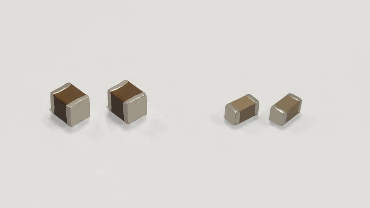
Samsung Electro-Mechanics secures record 1.07 trillion won AI server MLCC order, lifting 2027 LTA backlog past 3.3 trillion.
Samsung Electro-Mechanics Secures Largest-Ever MLCC Order
TI issues its fourth price hike in twelve months, with increases ranging 15%–85% on analog, MCU, and power management lines.
Analog Chip Leader TI Issues Another Price Increase Notice