Inverting Amplifier: Principles, Applications, and Development Trends
2025-05-14
In the realm of electronic circuits, the operational amplifier (Op-Amp) is an extremely important electronic component, widely used in various aspects such as signal processing and control systems. Among these, the Inverting Amplifier, as a common configuration of the Op-Amp, has a unique circuit structure and working principle that enables signal inversion and amplification. This article will delve into the basic concepts, working principles, structural composition, and application scenarios of the Inverting Amplifier, as well as its differences from the Non-Inverting Amplifier. Additionally, we will introduce popular Inverting Amplifier IC models and their development trends.
What is an Inverting Amplifier?
An Inverting Amplifier is a circuit configuration based on an operational amplifier, with 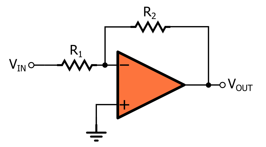 the core function of amplifying the amplitude of the input signal while causing the output signal to be 180° out of phase with the input signal. This circuit is simple in structure but powerful in function, and it is widely used in scenarios where signal inversion and amplification are required. For example, in audio processing, the Inverting Amplifier can be used to improve the phase characteristics of audio signals; in industrial control systems, it can be employed for signal conditioning to enhance the system's sensitivity and dynamic response.
The working principle of the Inverting Amplifier is based on the negative feedback mechanism of the operational amplifier. The input signal is connected to the inverting input terminal (negative end) of the operational amplifier through a resistor R1, while the non-inverting input terminal (positive end) is usually grounded. A portion of the output signal is fed back to the inverting input terminal through a feedback resistor R2, forming a negative feedback loop. This negative feedback mechanism not only stabilizes the gain but also ensures that the output signal is out of phase with the input signal. The gain is determined by the ratio of the resistors, with the specific formula being −R1/R2. The basic circuit of an Inverting Amplifier consists of an operational amplifier, an input resistor R1, and a feedback resistor R2. In some cases, capacitors may be added to the circuit to improve frequency response or filtering effects.
Furthermore, based on the ratio of the feedback resistor to the input resistor, the Inverting Amplifier can be categorized into three basic types:
- Inverter (Phase Inverter): When R2=R1, the gain is -1, and it only performs the function of signal inversion.
- Inverting Amplifier: When R2>R1, it achieves both signal inversion and amplification.
- Inverting Attenuator: When R2
The application scenarios of the Inverting Amplifier are extremely broad, mainly due to its simple structure, stable performance, and strong anti-interference capability. In audio equipment, it is used to enhance the amplitude and frequency of audio signals to improve sound quality; in the field of industrial control, it is employed for signal conditioning and control systems to enhance system sensitivity and dynamic response; in instruments and meters, it is used for signal amplification and phase inversion to meet specific measurement requirements. In addition, the Inverting Amplifier is also widely used in communication systems, medical devices, and consumer electronics.
Inverting Amplifier vs. Non-Inverting Amplifier
When we talk about the Inverting Amplifier, it is often compared with the Non-Inverting Amplifier. In particular, in operational amplifier applications, the Inverting Amplifier and the Non-Inverting Amplifier are two of the most fundamental circuit configurations, and they have significant differences in performance characteristics and application scenarios. Understanding the differences between these two types of amplifiers is crucial for circuit designers to make reasonable choices. The main differences are as follows:
- Input and Output Phase Relationship: The output signal of the Inverting Amplifier is 180° out of phase with the input signal, while the output signal of the Non-Inverting Amplifier is in phase with the input signal.
- Input Signal Connection: The input signal of the Inverting Amplifier is connected to the inverting input terminal of the operational amplifier, while the input signal of the Non-Inverting Amplifier is connected to the non-inverting input terminal.
- Gain Calculation: The gain of the Inverting Amplifier is -R2/R1, while the gain of the Non-Inverting Amplifier is 1 + R2/R1 .
- Input and Output Impedance: The Inverting Amplifier has a lower input impedance and a higher output impedance, while the Non-Inverting Amplifier has a higher input impedance and a lower output impedance.
Comparison of Main Characteristics between Inverting and Non-Inverting Amplifiers
|
Characteristic
|
Inverting Amplifier
|
Non-Inverting Amplifier
|
|
Input Impedance
|
Low (equal to R1)
|
Very high (close to the op-amp's own input impedance)
|
|
Common-Mode Voltage
|
Almost zero (virtual ground)
|
Equal to the input signal voltage
|
|
Anti-Interference Capability
|
Strong (only differential mode signals)
|
Weaker (dependent on the op-amp's CMRR)
|
|
Gain Range
|
Any value (can be less than 1)
|
≥1
|
|
Phase Relationship
|
Inverted (180°)
|
Non-inverted (0°)
|
|
Noise Characteristics
|
Low equivalent input noise
|
May introduce common-mode noise
|
Popular Inverting Amplifier IC Models
In modern electronic design, Inverting Amplifiers can be built using general-purpose operational amplifiers or directly using specialized integrated IC solutions. There are many popular Inverting Amplifier IC models on the market, each with unique performance characteristics. Understanding these mainstream IC models and their key parameters can help engineers make reasonable choices in actual projects.
|
Model
|
Type
|
Key Features
|
Typical Applications
|
|
AD8615
|
CMOS Op-Amp
|
Low noise, rail-to-rail, high slew rate
|
High-precision signal conditioning
|
|
AD5270/AD5272
|
Digital Potentiometer + Op-Amp
|
1024-level digitally programmable gain
|
Programmable instruments and meters
|
|
JFET Input Op-Amp
|
High input impedance, low noise
|
Audio processing
|
|
|
Logic Gate/Inverter
|
3V~16V operating voltage
|
Digital signal inversion
|
|
|
NC7SP04P5X
|
ULP Inverter
|
0.9V~3.6V, 0.9μA static current
|
Portable devices
|
|
OPA1656
|
Audio Amplifier
|
Low distortion, high dynamic range
|
High-end audio equipment
|
Development Trends of Inverting Amplifiers
As a fundamental circuit structure in the field of electronic engineering, the development trajectory of Inverting Amplifiers is closely related to semiconductor technology, signal processing requirements, and system integration trends. In recent years, Inverting Amplifier technology has shown clear development trends in multiple dimensions. These trends not only reflect the overall direction of the electronics industry but also indicate that Inverting Amplifiers will play a key role in more emerging fields in the future.
- High-Performance Integration: With the advancement of semiconductor technology, the performance of Inverting Amplifiers is continuously improving, such as lower noise, higher gain precision, and lower power consumption. At the same time, integrated design makes Inverting Amplifiers more compact and easier to use in compact devices.
- Intelligence and Programmability: Modern Inverting Amplifiers increasingly adopt digital control technology, supporting software programming to adjust parameters such as gain and bandwidth. This intelligent design enhances the flexibility and adaptability of the circuit.
- Multi-Function Integration: The integrated design of Inverting Amplifiers with other functional modules (such as filters and oscillators) is becoming more common. This multi-function integration not only reduces circuit complexity but also improves the overall performance of the system.
- Green and Energy-Efficient: Against the backdrop of increasingly strict environmental requirements, low-power design has become an important development direction for Inverting Amplifiers. By optimizing circuit design and using new materials, Inverting Amplifiers can significantly reduce power consumption while maintaining performance.
In summary, the Inverting Amplifier ic, as an important electronic circuit, has been widely used in various fields due to its unique signal inversion and amplification functions. It has its own characteristics compared to the Non-Inverting Amplifier and is suitable for different application scenarios. With the continuous advancement of technology, Inverting Amplifiers are developing towards high performance, intelligence, multi-function integration, and green energy efficiency, providing a solid foundation for the progress and innovation of electronic technology.
Email: info@semicone.com
Apple Enters Brain-Computer Interface: Is Mind-Controlled iPhone the Future?
NVIDIA's Global Price Adjustment: A 25% Uptick in GPU Prices
Related Article

Current sense amplifiers turn tiny shunt-resistor drops into precise voltage outputs. Learn high/low-side sensing, key specs, and top CSA models.
Current Sense Amplifier: A Complete Guide from Principles to Selection

Resonac unveils Japan's first 12-inch SiC substrate, delivering 4x the chip output of 6-inch wafers. AI server cooling and AR waveguides are key targets.
Power Semiconductor Materials: Resonac's 12-Inch SiC Substrate